Week 1: Nuke 3D and Camera Projection
Back to my second office now Univesity, things going great and is time to learn some more Nuke. Today's lecture was about 3D in Nuke. We watch a short video about Avatar a James Cameron movie, here we saw a couple of examples of how compositing is used in the cinema industry and how simple things are when you know how to use the right tools for it.
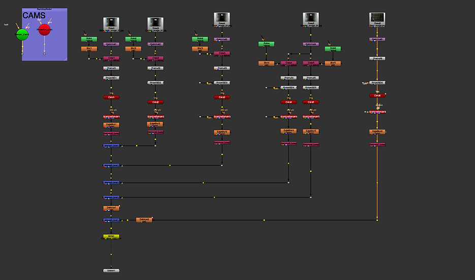
This image shows the structure we were following in class through the graphic node view.

Intro into 3D in NUKE


First Practice: The Tunnel


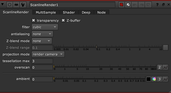
Scanline: the New node
Tunnel Process
Node Graphic

Tunnel Done
Second Practice: The Cell
Cell Process
Graphic Node
Cell Done
Week 2: NUKE 3D TRACKING
This week's topic was 3D Camera Tracking. 3D Match Moving, as previously discussed, is the process of blending live backplate footage with CGI so that they match. A 3D Match Moving algorithm is used to detect patterns in pixels and follow them across the screen as a result of mapping live backplate footage into a 3D environment. We'll have to fix lens distortion caused by the lens to have a 3D camera that tracks correctly. This will be a problem as we will need to create a three-dimensional camera from points and recreate the motion.
This week was also divided into different exercises.
Task 1.
Card
Task 2.
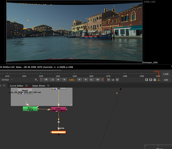
Venice tasks Process
Windows, RotoPaint
Graphic Node
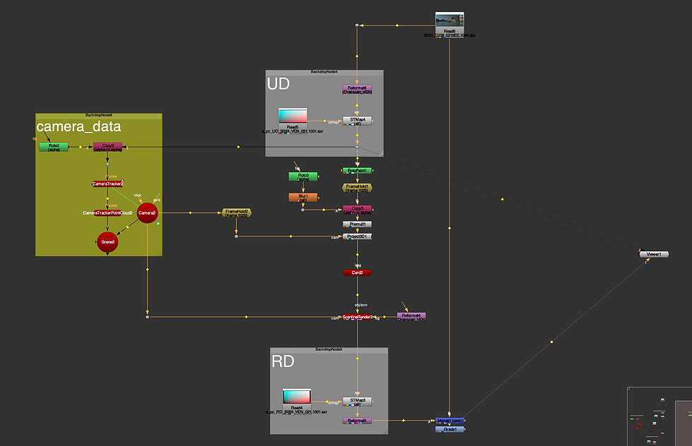
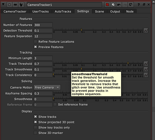
Camera Tracker:
Tracking camera movement in a 2D footage allows you to add virtual 3D objects to your 2D footage by creating a virtual camera which moves with the movements of your original camera. CameraTracker was designed to provide you with an integrated tracking and matching tool, enabling you to track the movement of virtual cameras.
Since the water is moving, tracking this area would be difficult. I positioned the Copy and Roto nodes above the CameraTracker node and masked this area out just above the water and people. To create a scene node, click on the 'Create' button on the Export window, then click on the 'Source Alpha' option and set the range before clicking 'Track and Solve'. Once the area is masked out, you will have an animated camera, a point cloud from the 3D points, and a Scene node.

Placing the card on the scene:
As a result of selecting wipe mode for the PointCloud camera view, I placed two viewers. As a result of selecting Vertex Selection Mode for the Card node, the vertexes were highlighted and a new Card was created. Scanline render node connected to Card and Camera nodes. Using the RotoPaint node, I put a color patch around one of the windows, set FrameHold to the dot, and set Frame 1025 where no blur is present. Next, I placed a clone tool around one of the windows to paint out.
Connected the Copy node to FrameHold and used the vertex around the window selected from PointCloud viewer to place the Card node. Rotated and resized the Card node to fit the size of the window from the Top viewer.


Week 3: 3D EQUALIZER.
This week we started to use 3D Equalizer, this software is the most used in the film industry just for tracking reasons is considered one of the best. We were looking at the workflow in 3D equalizer and the different interfaces.
Hotkeys setup
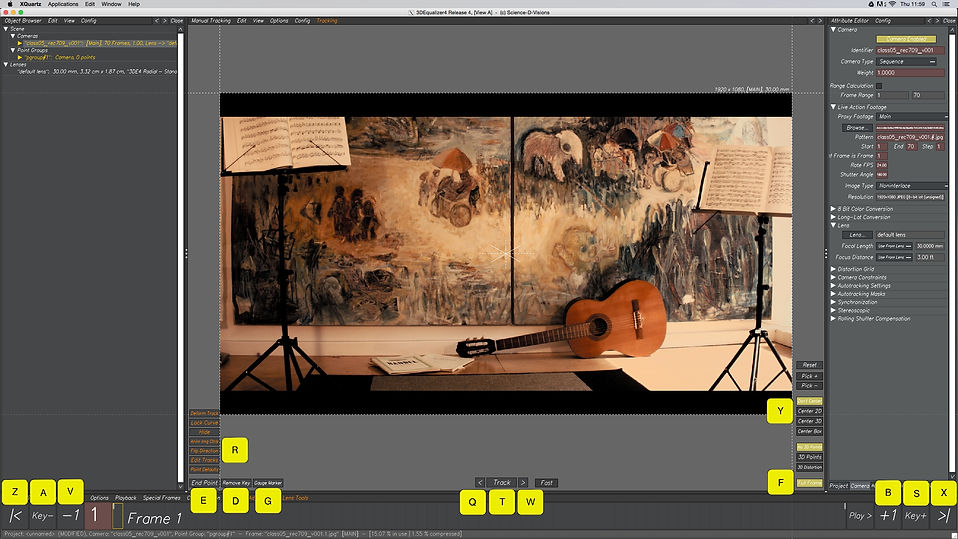
First tracking

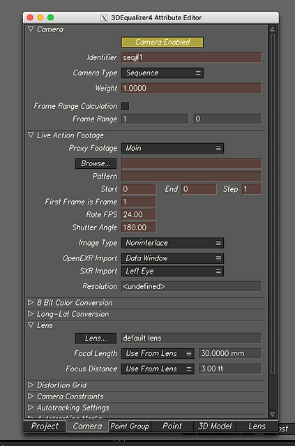
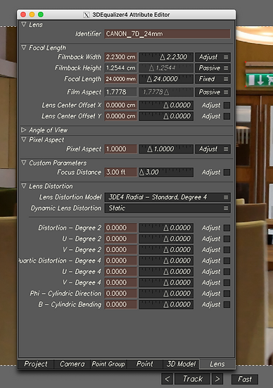
Set camera & lens & Filmback

Second tracking
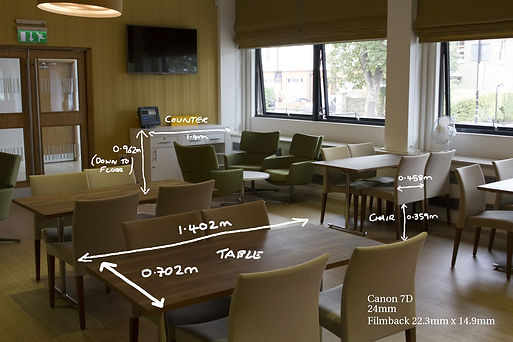
Week 4: LENSES & CAMERA
Camera settings, height following the survey data, and creating distance constraints. Also, we will need to put the survey data in 3D Equalizer to reach a precisely tracking.

Survey Data
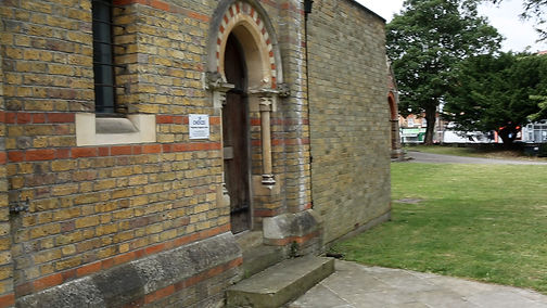
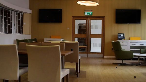
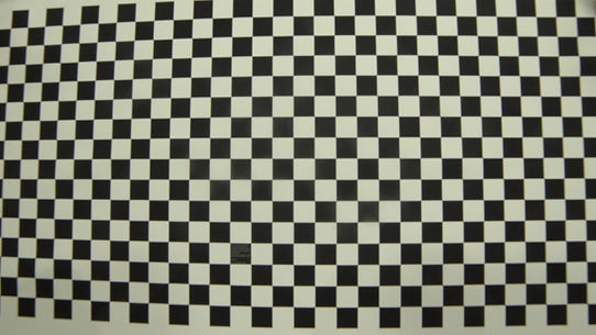
Raw footage
Lenses and camera setting process
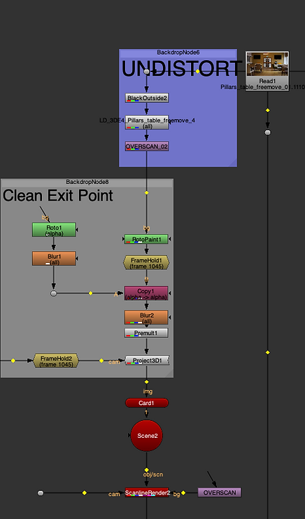
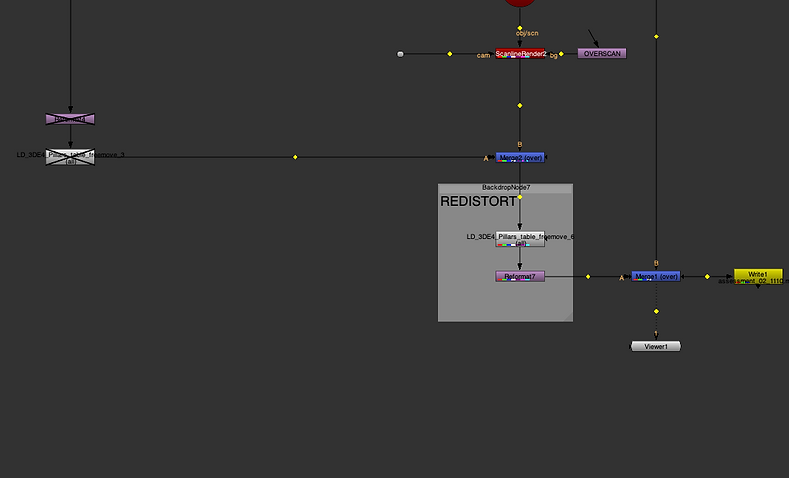
Week 5: 3DE FREEFLOW & NUKE
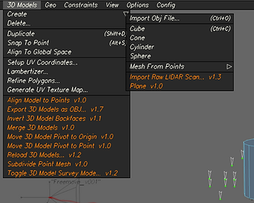
3D Object into the scene

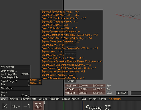
Bake the scene in 3DE export out the assets to use everything in Nuke. The process will be to export the locator, camera, 3D objects and the lens distortion, also following a specific workflow for lens distortion in Nuke, if this is not working is probably because you did not instal the plugins in Nuke.
3D Object: scale, rotation, translate in the 3D space


Exporting the LD to Nuke

Exporting Camera

Freeflow To Nuke Process
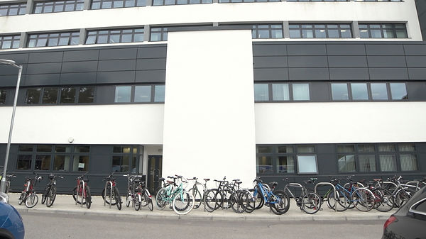
Assignment_01
TASKS:
-
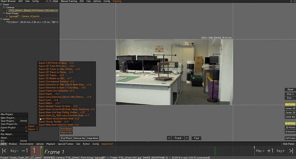
Minimum 40 tracked points.
-
Use whatever method is required to get a low deviation and therefore a solid track (e.g. lens distortion and focal length adjustments).
-
Solve and align scene in 3DE using survey data.
-
Add in locators and 3D Cube to test stability of solve.
-
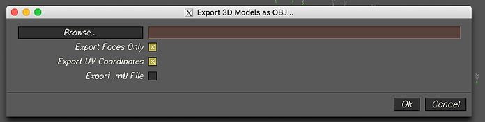
Export camera, LD data, locator geo, and 3d models to Nuke.
-
Undistort lens and reformat.
-
Place cleanup patch on the fire exit sign.
-
Overlay locators and 3d model to highlight strength to track.
LOCATORS EXAMPLE
FOOTAGE EXAMPLE

SURVEY DATA
Camera settings after using the Survey Data
3DE Process
Nuke Process
Final Outcome
Graph Nodes


Week 06: Surveys
Using precise survey data, I was able to create specific tracking points within 3D space using the data from measurements and camera info taken on set, in the video, for this week you will be able to see the entire process, that It will make our tracking technique more precisely.

Set
Survey Data
Tracking process, 3D equalizer

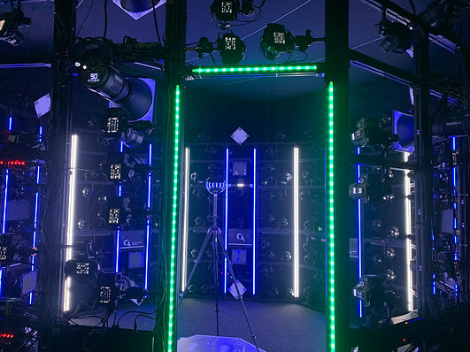
Week 07: Filming session for assessment 02
Week 7, during this time we went to the studio, using a green screen, and markers we were able of created a scene to be tracked later on with 3DE. This session was planned to make us familiar with the process and steps that you must follow on set to get every piece of data, that later on will be use for you project.


Original Clip
Week 08: Survey Data
Week 8, was a continuation of week 6 we took more in deep survey data, were using different images we located the same tracking points, to link better out track and make the link more sable. By the end of the lecture, we had 30 tracking points using different images as references.
Week 09: Lens Distortion and Grids.
Lens distortion in 3D using the grid this time to help us with the lens distortion, this is mostly used on set where the VFX team (data wranglers) and the DP team will share data of the lens. Today we tracked 26 points and we used the grid to generate and fix the distortion of the lens.
Lens distortion process with the grid.
Week 10: Workflow Nuke To Maya.
Week 10 was about the entire pipeline and one last practice before the assessment to recap every single step within the pipeline to bring our 3D character and tracking scene together as one scene. going through 3DE, then Maya and last Nuke. applying.
3DE exporting Data to Maya


3DE to Maya and Maya process
Maya to Nuke process
Final Render

Assessment_02
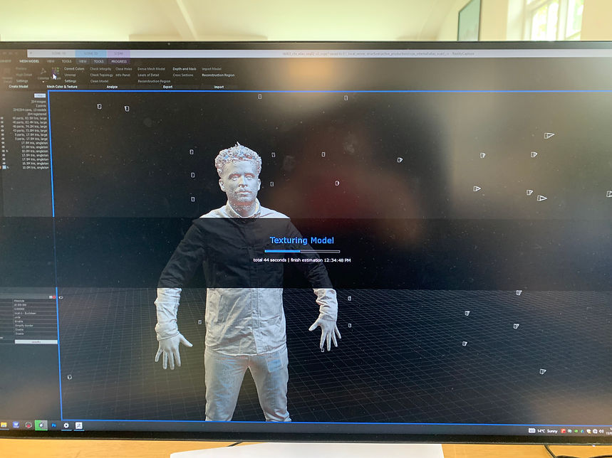
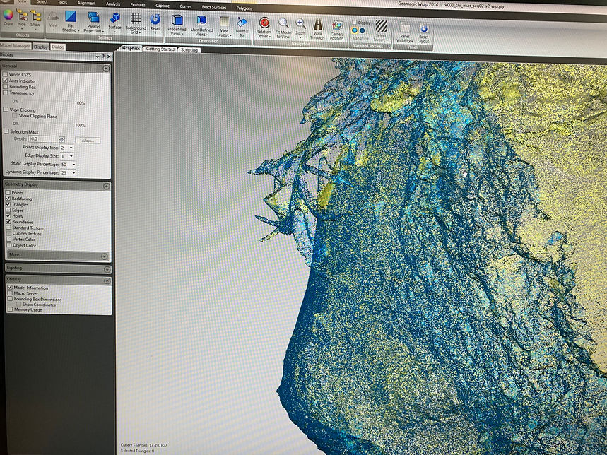
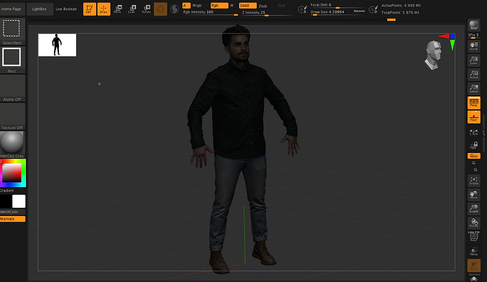
Assessment 2 it will be a combination of multiple techniques, where I have also include Clear Angle Tech. basically the idea is to use everything I have learned so far in Clear Angle Studios, and university and put everything together in to a massive project. Following the pipeline from 3D scanning, Reality capture, cleaning the mesh in Wrap and Zbrush,


Idea_process_on_set
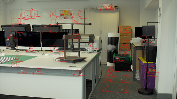
Fotage_sequence_process_01
3D_equalizer_tracking_process_02
Distorsion_calculation_focallenthg_process_03
Locators_distance_btween_objets_process04
Bringging_project from 3d_to_maya_process_05
Pipeline_3d_nuke_maya_process_06
Maya_import_scene_locators_fixing_focallenght_process_07
Zbrush process:
Maya_Arnold_render

Hdri_room_lighting_ref

Lighting_process_texturing_render
Test_01


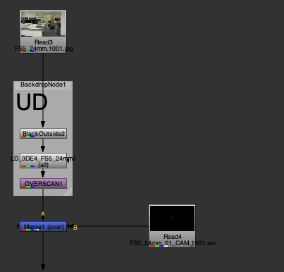
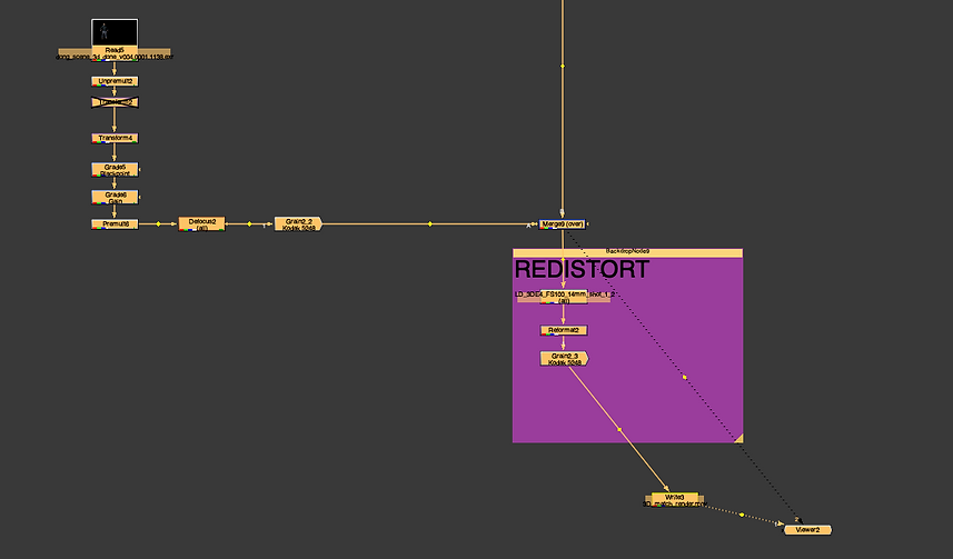
Node_UD_to_DS_08
Connecting_the_Nodes_from_3DE_to_highlight_distortion_09
Creating_a_Patch_based_from_info_from_3DE_010
3D_chracter_to_nuke_grading_11
First Test
Graph Node


Final Render
Final Node
